Background
Since getting my amateur license in 2023, I’ve been active on VHF in Sydney using a handheld but my home locations weren’t suitable for a HF station.
After accepting that I will be restrained to operating portable for the foreseeable future, I finally pulled the trigger on setting up my first portable HF station in the last few weeks.
I hold a Foundation class license at the moment which applies some restrictions to my usage of the HF bands and the station setup I’m initially running:
- Power limited to 10 watts
- Access limited to:
- 3.5MHz-3.7MHz on 80 metres
- All of 40 / 15 / 10 metre bands
I’m planning to study for the Standard and Advanced classes so that I can unlock all bands, but while I’m learning the ropes, I am fine working low power SSB voice and playing with FT8. I’d eventually love to try CW when I get my head around it.
Picking the radio
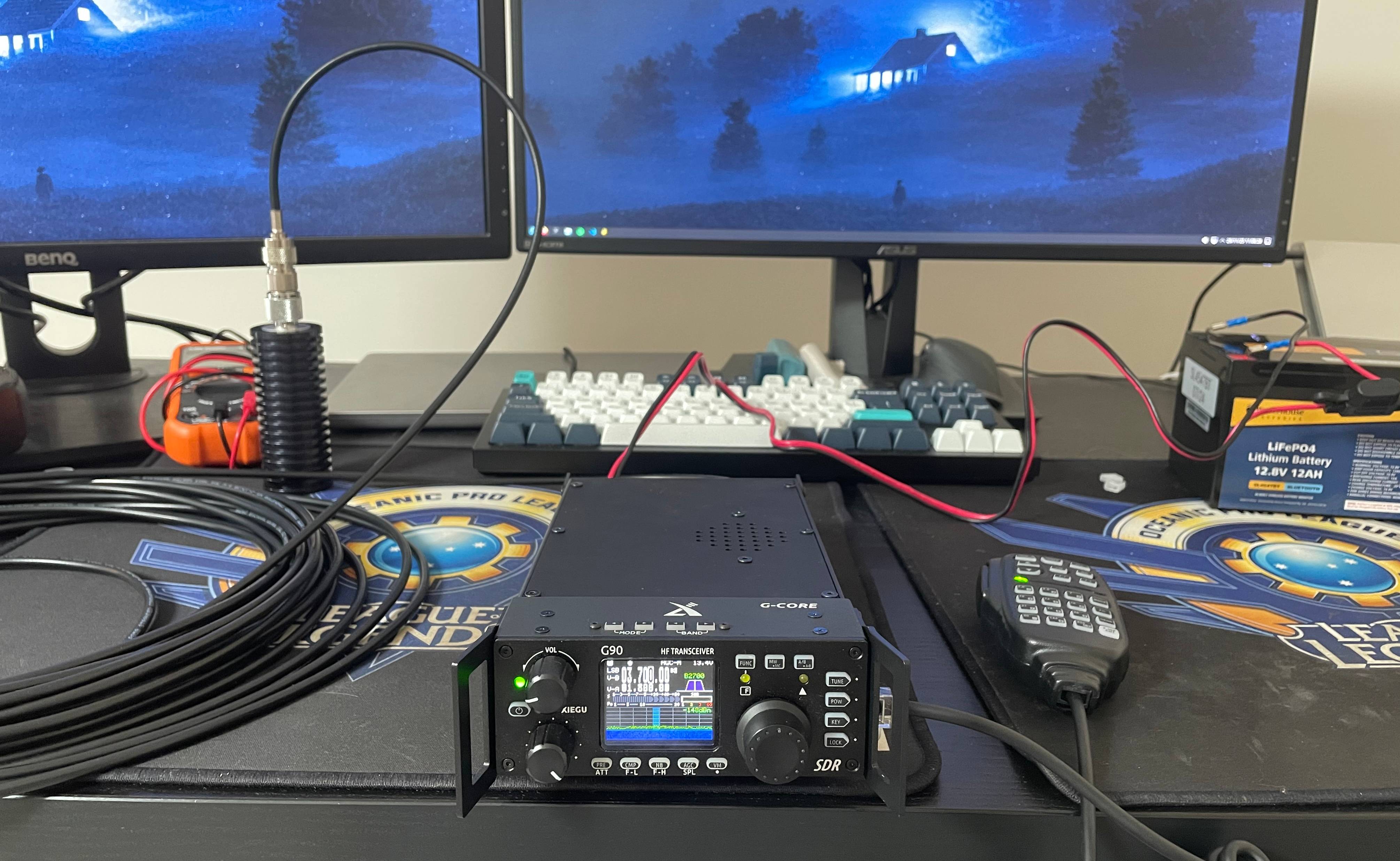
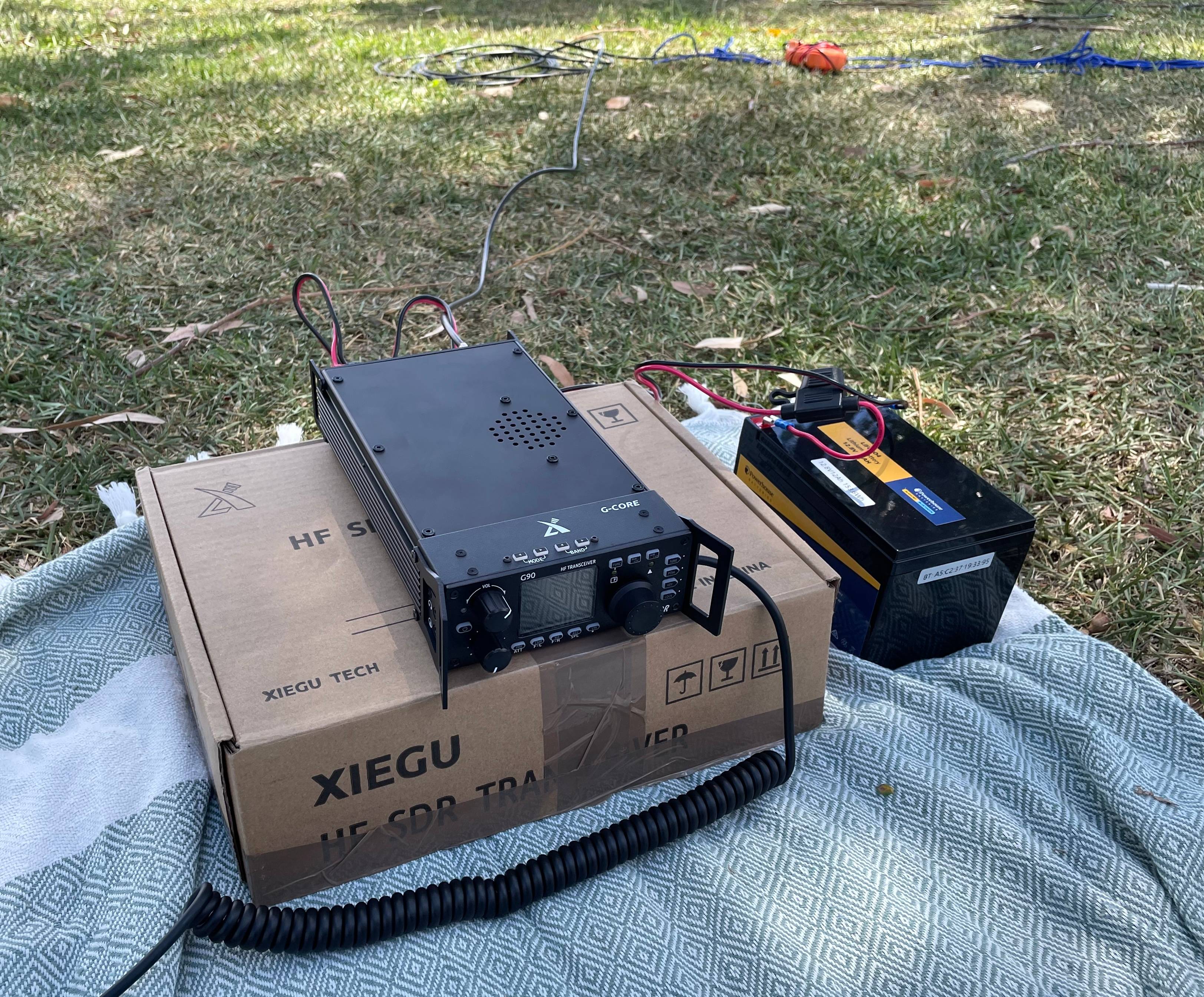
I picked up an ex-demo Xiegu G90 at Picton Hamfest which can operate on all HF bands & all modes. The G90 has a maximum power of 20W. That’s double my power limit as an F-call, so this will be great for me at the start.
I can see the G90 still being used for mobile work when I get a higher license class, so I picked it over getting a lower power rig like the Yaesu FT-817.
The feature set is probably easier to learn, and the price was much less aggressive on the wallet than the full fat IC-7300 I was drooling over at a neighbouring booth. The G90’s form factor definitely lends better to portable operation out of a backpack when compared to the IC-7300!
Although if I could’ve gotten my hands on a Yaesu FT-897D, it would have been a different story…
I additionally picked up a 12Ah LiFePO4 battery and charger online to drive the radio.
Designing the antenna
With the radio locked in, I moved onto building a half-wave dipole antenna for 40 metres. I was hoping this would work decently on the 15 metre harmonic with some help from the G90’s built-in tuner.
I am aiming for a centre frequency of 7.150 MHz which will require two quarter-wave lengths of wire as close to 10 metres in length as possible, forming a half-wavelength for 40 metres. My tape measure maxes out at 8 metres, and I want to leave extra length for cutting the wires to tune, so I’m expecting to go over that length and adjust back.
The dipole was designed to be rigged using trees and would be deployed as an inverted-V in majority of cases, as I was hesitant on my ability to get 3 symmetric lines secured at a 8-10 metre height in multiple trees. In the inverted-V configuration, I would only need one high line for the antenna box, and each antenna end can be secured closer to the ground quite easily at the right angle.
I didn’t have many tools to start with, however I plan on building a fair few antennas after the joy of building this first one, so the decision to buy these wasn’t a hard one. The upfront researching and locating of all the tools and parts was really the bulk of effort in this antenna build. It feels like Google is only getting worse and worse by the day.
Here’s a list of the parts I used for the antenna itself:
- 75x75x55mm junction box
- SO-239 connector
- 4x PL-259 crimped plugs for RG-58
- Two were backups which I definitely needed
- 18awg enamelled copper wire
- This was ultimately the wrong pick as antenna wire, for reasons outlined later. Great for baluns, ununs or transformers though.
- 20m RG-58 coaxial cable
- I thought this was RG-58/U with a solid centre conductor, but it was actually RG-58C/U with a stranded centre conductor. Would not recommend if you’re crimping.
- I ended up cutting the final feedline down to around 15m as I don’t need the extra length right now.
- 1m of 3-core 18awg cable
- I thought “that’s 3 metres of cable for the price of 1 metre” when buying this for short jumper cables but it was very late at night.
- It turns out there’s a lot of ambiguous powdered insulation inside these cables which make for a fun time when stripping the outer PVC. Quite the mess. I’d compare it to opening up an anthrax letter.
- Go buy some hook up wire instead, which can be used as antenna wire too instead of enamelled copper.
- 2x plastic electric fence insulators
- 2x 30 metre lengths of para cord from Bunnings
- Steel tent pegs
- M3-M5 nut and bolt set
- M3-M5 wing nut set
- Lug crimp set
- 1x M6 eye bolt (random from Bunnings)
- M3 and M6 washers (random from Bunnings)
I purchased a FT-240-31 mix ferrite toroid with the intention of building a 1:1 balun inside the antenna box, however this didn’t arrive in time for my testing. It will be installed in future.
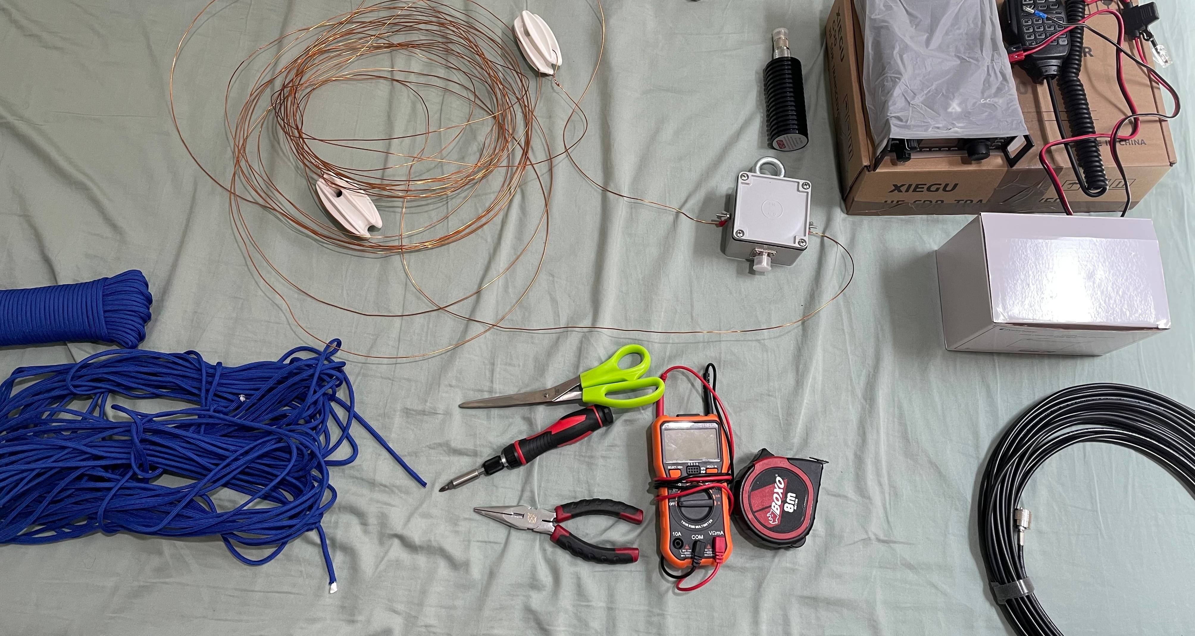
And here’s a list of most tools that I used for the build:
- Multimeter
- My previous meter sucked so this was a good excuse.
- RG-58 crimp tool
- RG-58 coax stripper
- 18awg wire stripper and crimper
- Step drill bit set
- Wouldn’t go using this for anything hard or important, but it works bloody great for plastic at the low price of $13.
- M2 & M3 drill bits
- A drill (shock horror)
- Ratcheting screwdriver set
- I thought this would be terrible but it’s actually not bad. Semi-unrelated to the antenna. It still gets an honourable mention.
Building the antenna
After giddily waiting for my packages to arrive and making several visits to Bunnings, I started assembly without the ferrite so I could still test everything and practice operating to get some knowledge.
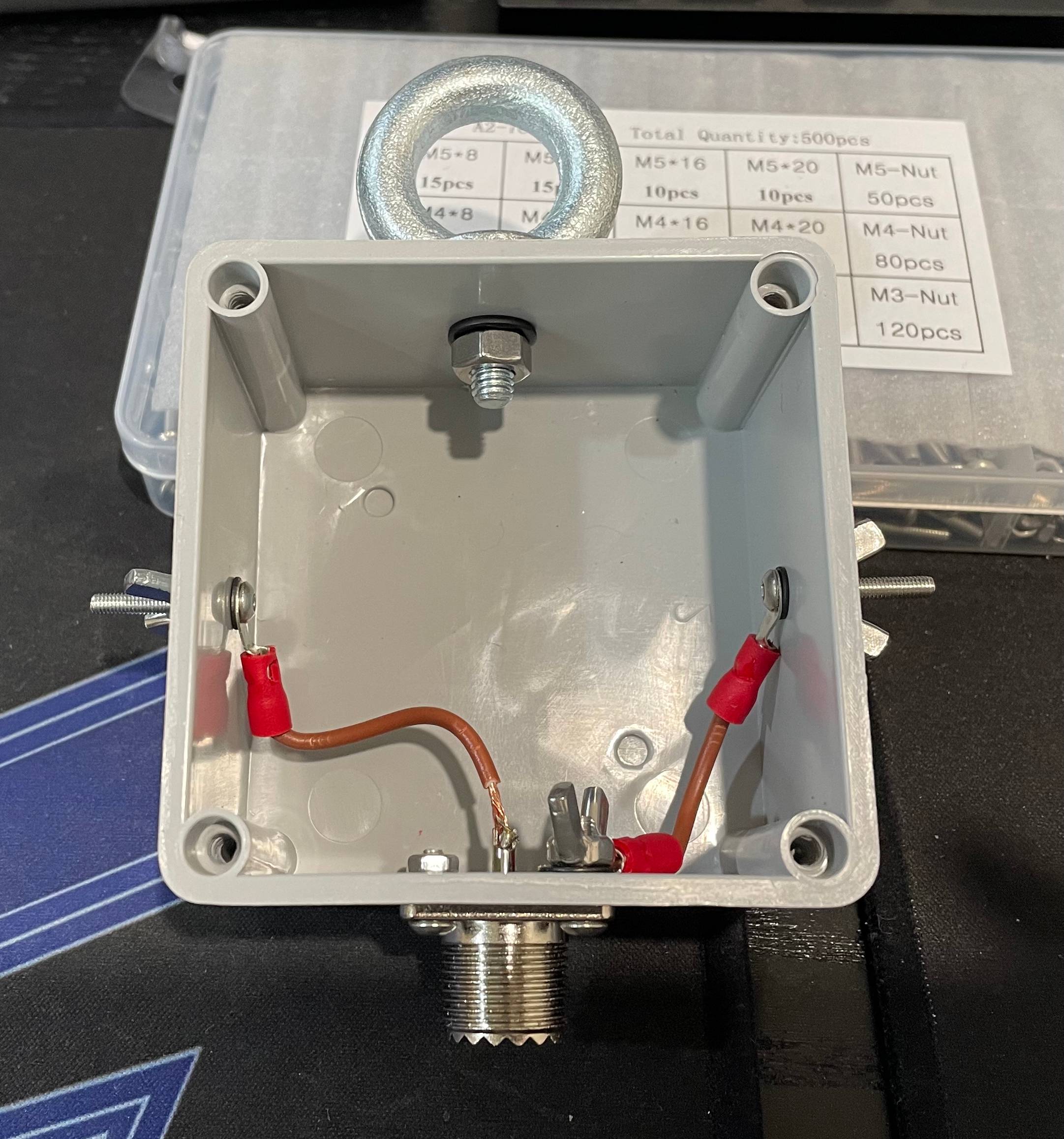
The base of the antenna box uses a 75x75x55mm plastic electrical junction box, which is just large enough to house the ferrite toroid and still provide enough space for termination points. The box is IP-56 rated, but I suspect my haphazard drilling and fastening will void that rating.
I started by marking holes for the 6mm top eye bolt, 16mm bottom SO-239 center hole, and the two 3mm bolts on each side for terminating each antenna wire. The 6mm and 16mm holes were drilled with a very cheap step drill bit but came out perfectly fine; any roughness was due to my own handiwork.
After drilling the 16mm hole, I inserted the SO-239 connector and marked the 4x mounting holes, then drilled these out to 3mm diameter.
I then installed the eye bolt with M6 washers & nuts. The SO-239 and side termination lugs used M3 bolts, nuts and washers. One M3 bolt on the SO-239 was a longer length to make hooking my coax shield lug wire a bit easier.
I made 2 short cables out of 18AWG insulated wire and crimped ring lug terminations onto these cables. Each cable connects to an antenna wire via the termination lugs on each side of the antenna box, and wingnuts are used so the wires can be easily adjusted in the field.
One cable is connected with a lug nut to the shield bolt, the other cable is soldered directly to the centre pin of the SO-239 connector. The solder job was terrible but it holds up for a test, and I know what needs adjusting next time for a better connection. It will be swapped out when the ferrite toroid is installed, or when it breaks; whichever comes first.
I cut two very badly measured 10m lengths of enamelled copper wire for the antenna elements, and this was the start of my regret. I was cutting indoors with roughly 3 metres of space, and the wire is not cooperative. That was obviously not an accurate decision, and is another point on the scoreboard for using a PVC insulated wire in future.
Each antenna wire had one end wound back in a loop around a plastic electric fence insulator, and the other end was crimped to a ring lug that connected to the termination lugs on the antenna box. One of these crimps came out perfect, but I messed up the other crimp and slightly cracked it. The cracked connector held after a tug test, so I thought it might have a chance of holding up in the field.
With the antenna assembled, I cut a ~15 metre length of RG-58 coaxial cable and crimped on two PL-259 plugs. I bought a cheap coax stripper which doesn’t retain it’s blade alignment between attempts, so it took a few tries to get this right. Not to mention the initial short circuit I created inside the cable due to a bad crimp - always test your cables with a multimeter before use!
I powered up the radio for the first time while hooked up to a dummy load to further test the coax and ensure that all radio functions were working fine. This was a great time to practice different radio controls that I’d learned while reading the manual before I took it out into the field.
Testing the rigging
Screwing the antenna box together, I packed my entire portable setup into two bags and went down to a local park for a test run.
Packing the rigid wire was tough, and the end result was an inter-dimensional tangle that didn’t care for how carefully I wrapped and secured the wire in my backpack.
My plan for launching the lifting line was pretty dodgy. It involved a partially filled water bottle and a good underarm throw, but long term I think it will need to be launched using a fishing rod and weight attached to heavy-duty line as a leader for my rigging. Slingshots are unfortunately considered prohibited weapons in New South Wales so that option is off the table, but an arborist’s throw bag might be something to explore as well.
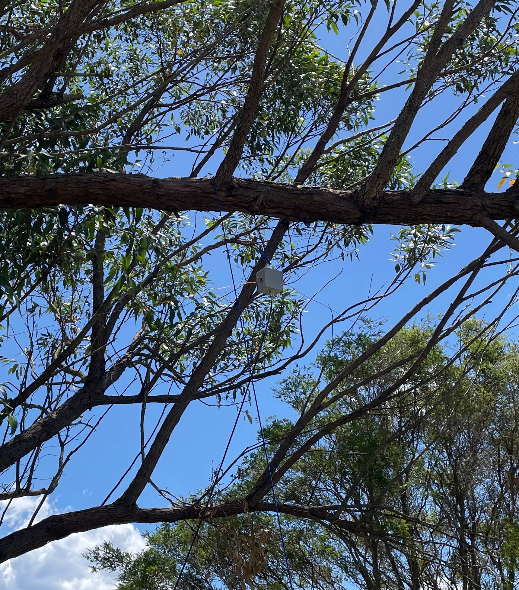
To rig the antenna, I would attach para cord to the antenna box and insulator ends. The antenna box would be lifted into the high branch after launching and all lines would be secured with tension to a tent peg.
It turns out that tree options in my nearby area aren’t great, and it was decently windy afternoon. Launch attempts at high branches were not successful in the wind, which led me to settle on getting it up into a branch only 3.5-4 metres high, just so I could continue testing and not worry too much about the lack of contacts.
Rigging the dipole isn’t too difficult as a single person, but the enamelled copper wire’s tendancy to retract and tangle made for a frustrating time. I spent most of my setup time untangling wire and para cord. I can’t find the balance with winding the enamelled wire up for storage, and then straightening it out as a single person. This is the part I start cursing myself for not buying more flexible wire.
My termination lugs need improvement as they have a tendency to unscrew themselves when you’re trying to fix the antenna wire onto them. This isn’t a massive problem, but if unscrewed too much, it had the potential to rip the internal wires away from the SO-239 connector and requires opening the junction box to tighten them again. I believe some lock nuts would fix this up and make the termination lugs more rigid.
Once I had straightened the wire and tensioned the insulator ends with paracord into a shape resembling an inverted-V pattern, I hooked the coax into my radio and watched as the antenna wire connecting to my ground shield immediately separated from it’s terribly crimped ring lug and clattered to the ground.
This needed a quick pull-down-and-repair by wrapping the wire around my terminating lug to bypass the crimped connection entirely. After some happy beeps from the multimeter, I hoisted the antenna up and fired up the radio after making sure the wind wouldn’t snap anything again.
Firing up the radio
The SWR scan showed 3:1 to 4:1 across 7-7.3MHz, which I’m assuming is a combination of my antenna wires being too long and my antenna being far too close to the ground.
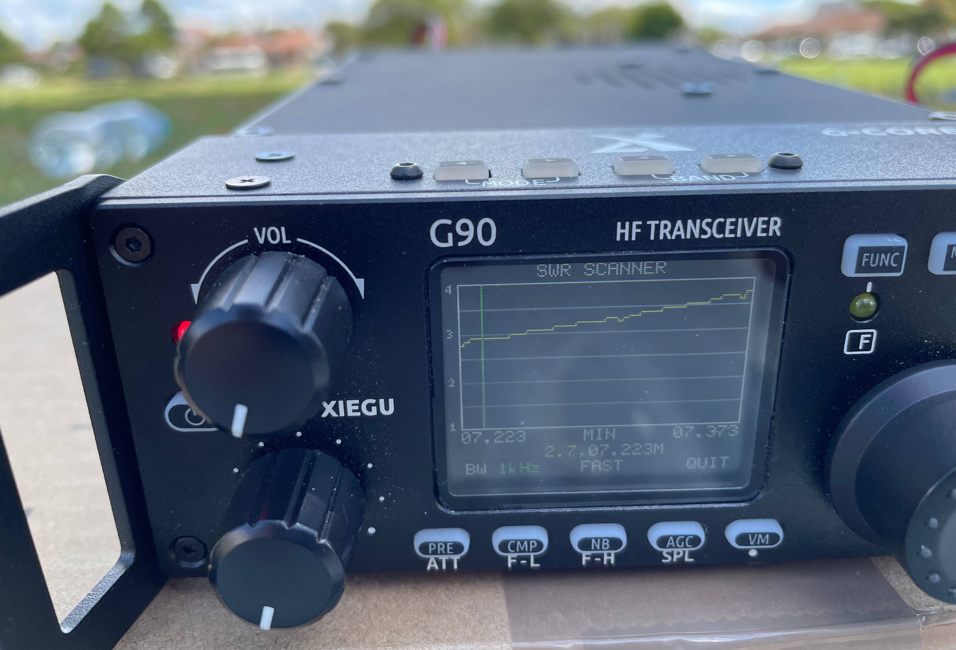
I adjusted element lengths but wasn’t getting great results between scans, so I stopped before I made it worse and hit the G90’s ATU to start searching for signals to hear.
Immediately I heard some FT8 data signals on 40 metres at 7.074MHz. After a bit over an hour of surfing around, I had heard some chatter on 15 metres, and a few people on 40 metres testing and doing POTA activations.
There were weaker signals that weren’t discernable, and ultimately I’m assuming that I was only hearing some very powerful or local signals with the antenna mounted so low and without lengths being optimised.
I keyed up for a while but didn’t really get out anywhere, which I’m not surprised about given the dipole is mounted close to ground level, but I was happy to hear signals and see that everything worked and nothing exploded.
However, it was clear the main challenge of this dipole would be reliably rigging the center at height if using trees, which also meant finding good locations with suitable trees. All while ensuring I can avoid snags and not leave any waste behind.
Learnings and future plans
Any wire is good wire, but make sure it’s not too rigid for your application and isn’t a complete pain in the ass to work with.
Long lengths of para cord will tangle themselves when your head is turned if not carefully wrapped and tied. Try to cut smaller lengths of para cord that are only as long as necessary, and be vigilant about wrapping it when not using it to save yourself untangling time later.
As a new operator, I think it’s more important to prioritise getting on the air in any capacity, rather than stressing over doing it perfectly. I learned more about setting up and operating a HF station with this quick test than I did by purely researching, and that’s with all the failures and bad decisions. I wish I would’ve pulled the trigger on a portable setup ages ago.
When I assessed building a dipole against a vertical, I thought the difficulty of getting a single rope into a tree would be worth using a more “ideal” antenna over a vertical with counterpoise wires. Especially with my misunderstanding of how many counterpoise radials would actually be required for good operation using a vertical.
I’ve decided that while I think more about the rigging of my dipole when using trees, I’m going to buy a 10 meter telescoping “squid pole” to support a vertical antenna with 4-6 radials to experiment with that, and return to complete the dipole over time.
Ideally I would like to get the antenna box light enough to hang it from the squidpole as this would eliminate trees as a whole and let me set up anywhere with enough open space.